OK made a bit of a breakthrough on this. I bought a PAYG Orange SIM for my Nokia, put £5 on it and was able to communicate with it using "Real Term" http://realterm.sourceforge.net I was able to send "ATD xxxxxxxxxxx;" and dial my other mobile phone.
Also, when I called the Nokia, pin 9 on the RS232 received a signal. This is the breakthrough, I was wondering how I was going to detect an incomming call!!.
The signal seems to be in the right form to be the input into the ringer, i.e. it goes ring..ring......ring..ring.....ring..ring
The Sparkfun RS232/MAX232 femail connector I bought to connect to the PIC only has 4 pins that have been made available with headers, but I can still get to the pin 9 from the underside of the circuit board.
Sunday, 23 June 2013

Ringer finished....
Just need to solder it up now and it's done :)
Wednesday, 19 June 2013
This is a variable frequency dual square wave generator. It simply uses a PIC to create 2 square waves 180 out of phase on ports B0 and B1. By turning the POT to vary the voltage into port A0, the analogue-to-digital converter creates an integer from the voltage, the frequency of the outputs is increased by turning the POT as shown in the above video. I don't have an oscilloscope so can't give an accurate frequency output, but I think it ranges from about 5Hz to 1000Hz.
The reason for this is to get the ringer as loud as possible, I initially tested it with square waves at about 22Hz fed into the H-bridge, but I don't think this is quick enough, so have included the ability to 'tune' the circuit with the frequency of the input voltage.
The code on the PIC 16F88:
#include <16F88.h>
#device adc=8
#FUSES NOWDT //No Watch Dog Timer
#FUSES INTRC_IO //Internal RC Osc, no CLKOUT
#FUSES NOPUT //No Power Up Timer
#FUSES MCLR //Master Clear pin enabled
#FUSES BROWNOUT //Reset when brownout detected
#FUSES LVP //Low Voltage Programming on B3(PIC16) or B5(PIC18)
#FUSES NOCPD //No EE protection
#FUSES NOWRT //Program memory not write protected
#FUSES NODEBUG //No Debug mode for ICD
#FUSES NOPROTECT //Code not protected from reading
#FUSES FCMEN //Fail-safe clock monitor enabled
#FUSES IESO //Internal External Switch Over mode enabled
#use delay(clock=20000000)
#use rs232(baud=9600,parity=N,xmit=PIN_A3,rcv=PIN_A2,bits=8)
void main()
{
int16 adc_value;
setup_adc_ports(sAN0|VSS_VDD);
setup_adc(ADC_CLOCK_DIV_8);
setup_spi(FALSE);
setup_timer_0(RTCC_INTERNAL|RTCC_DIV_1);
setup_timer_1(T1_DISABLED);
setup_timer_2(T2_DISABLED,0,1);
setup_comparator(NC_NC_NC_NC);
setup_vref(FALSE);
setup_oscillator(False);
while(TRUE) {
read_adc(ADC_START_ONLY);
adc_value = read_adc(ADC_READ_ONLY);
output_high(PIN_B0);
output_low(PIN_B1);
delay_us(adc_value);
output_low(PIN_B0);
output_high(PIN_B1);
delay_us(adc_value);
}
}
Monday, 8 April 2013
AT Command tests
As mentioned in the previous post you have to use Hyperterminal - there are others - e.g. minicom, but Hyperterminal seemed to be the most refered to in the Windows world.
Instructions can be found here:
http://www.developer.nokia.com/Community/Wiki/AT_Commands
The commands I am interested in are
ATDxxxxxxxxxx; // Dials a number - colon on end
AT+CHUP // Hangs up
ATA // Answer an incomming call
AT+CBC // current battery charge
When the Nokia rings the text "RING" is sent to the hyperterminal, it maybe possible to monitor for this or detect the signal sent to the ringer in the mobile phone to activate one of the inputs on the PIC - if this voltage is high enough then this may be the best option.
Could Include an option that will indicate the charge on the battery when a certain sequence is dialled. This could be 4 pips for full charge 1 for 25% etc.
Next step is to get a RS232/USB cable to check that serial commands can be sent - I'll use Minicom under Linux for this (just to make sure that the modem features of the Nokia 6301 are not "WinModem").
Instructions can be found here:
http://www.developer.nokia.com/Community/Wiki/AT_Commands
The commands I am interested in are
ATDxxxxxxxxxx; // Dials a number - colon on end
AT+CHUP // Hangs up
ATA // Answer an incomming call
AT+CBC // current battery charge
When the Nokia rings the text "RING" is sent to the hyperterminal, it maybe possible to monitor for this or detect the signal sent to the ringer in the mobile phone to activate one of the inputs on the PIC - if this voltage is high enough then this may be the best option.
Could Include an option that will indicate the charge on the battery when a certain sequence is dialled. This could be 4 pips for full charge 1 for 25% etc.
Next step is to get a RS232/USB cable to check that serial commands can be sent - I'll use Minicom under Linux for this (just to make sure that the modem features of the Nokia 6301 are not "WinModem").
GSM Module
I am sitting at my PC looking at www.proto-pic.com and their GSM module ADH8066. Seems that this is just what I need. I would also need an antenna and some method of connecting this or soldering to it. You can buy break-out boards which provide hardware interfaces, but this looks like it'll make the module quite big.
It then occured to me that all I need is an old mobile phone that is small enough to fit into the case of the old BT rotary phone.
It does everything for me:
The command strings to send to the phone are standard Hayes AT commands. I have worked out the one I need is:
ATD01233454567;
Simple as that this (don't forget colon on end) command dials via the com port on the mobile phone from a command string.
You can simulate this by bringing up Hyperterminal, or download it if using Win 7, and connecting the phone as a USB COM port - my laptop does not have an RS232 COM port so it is emulated via the USB. I will try the same with my Linux server that has an RS232 port on it. I will also possibly need a mini-USB to RS232 cable. I haven't worked out exactly how to connect the output of the PIC, which has interpreted and constructed the AT command, to the Nokia phone - I hope that it is as simple as connecting the right wire from the USB connector to the output pin of the PIC....more on this later.
The plan is to butcher the phone a bit, the screen is not needed, so I'll make this optional - hopefully using an AT command of some sort, but if not then I'll just pull some wires out. The battery will have to be used to activate the ringer as well so I'll have to tap into this. The mic and earphone will either utilise the existing BT phone ones or if they are active devices, which I suspect they are, I will try and use the jack plug with the 'hands free' ear & mic - simples!
Basicall that's it, the design is now as follows:
It then occured to me that all I need is an old mobile phone that is small enough to fit into the case of the old BT rotary phone.
It does everything for me:
- Battery power
- Charging
- Antenna
- Interface from COM port.
The command strings to send to the phone are standard Hayes AT commands. I have worked out the one I need is:
ATD01233454567;
Simple as that this (don't forget colon on end) command dials via the com port on the mobile phone from a command string.
You can simulate this by bringing up Hyperterminal, or download it if using Win 7, and connecting the phone as a USB COM port - my laptop does not have an RS232 COM port so it is emulated via the USB. I will try the same with my Linux server that has an RS232 port on it. I will also possibly need a mini-USB to RS232 cable. I haven't worked out exactly how to connect the output of the PIC, which has interpreted and constructed the AT command, to the Nokia phone - I hope that it is as simple as connecting the right wire from the USB connector to the output pin of the PIC....more on this later.
The plan is to butcher the phone a bit, the screen is not needed, so I'll make this optional - hopefully using an AT command of some sort, but if not then I'll just pull some wires out. The battery will have to be used to activate the ringer as well so I'll have to tap into this. The mic and earphone will either utilise the existing BT phone ones or if they are active devices, which I suspect they are, I will try and use the jack plug with the 'hands free' ear & mic - simples!
Basicall that's it, the design is now as follows:
 |
| Retro-mobile design |
Sunday, 24 March 2013
H-Bridge woes...
OK so I figured that the most fiddly bit would be the ringer circuit, especially the I have now blown up all three of my H-Bridges.
I think the problem is that they are only rated for a voltage of 36V and I am effectively feeding 57V in, it's low current so maybe it's OK, but for one reason or another I shorted or forgot to put a capacitor in to prevent feedback and whilst it worked briefly. I had to find a better solution.
There is another H-Bridge (NJM2670) that handles up to 60V, which would be ideal, but I can only find them at RS and they're £7 each and you've got to buy at least 2. This seems a bit of a con as they are available from US suppliers for $3!!
Anyway I decided to build my own H-Bridge from some NPN and PNP transistors.
This has the advantage that I can use more robust components - the NPN - 2N5682 can handle 120V and the PNP 2N6042 can handle 100V - should be good enough.
I downloaded LTSpice circuit emulation software and designed the circuit based on a classic design. I simulated it but never really got the output I expected, not sure if the transistors were slightly wrong or the other values were wrong or whether I was using the software incorrectly.
I built it anyway along with the 4 massive Schottky diodes - which has legs too thick to push into my breadboard (I soldered thinner wire to them - LOL).

Along with the square wave generator I programmed onto my PIC, the whole setup works. Although one of the NPN transistors gets very hot - I'm not sure why this is - maybe the tuning capacitor is causing this somehow.

I think the problem is that they are only rated for a voltage of 36V and I am effectively feeding 57V in, it's low current so maybe it's OK, but for one reason or another I shorted or forgot to put a capacitor in to prevent feedback and whilst it worked briefly. I had to find a better solution.
There is another H-Bridge (NJM2670) that handles up to 60V, which would be ideal, but I can only find them at RS and they're £7 each and you've got to buy at least 2. This seems a bit of a con as they are available from US suppliers for $3!!
Anyway I decided to build my own H-Bridge from some NPN and PNP transistors.
This has the advantage that I can use more robust components - the NPN - 2N5682 can handle 120V and the PNP 2N6042 can handle 100V - should be good enough.
I downloaded LTSpice circuit emulation software and designed the circuit based on a classic design. I simulated it but never really got the output I expected, not sure if the transistors were slightly wrong or the other values were wrong or whether I was using the software incorrectly.
I built it anyway along with the 4 massive Schottky diodes - which has legs too thick to push into my breadboard (I soldered thinner wire to them - LOL).

Along with the square wave generator I programmed onto my PIC, the whole setup works. Although one of the NPN transistors gets very hot - I'm not sure why this is - maybe the tuning capacitor is causing this somehow.

Work so far
All I've got to do now is solder this up making it small enough to fit inside the casing.
Sunday, 17 March 2013
Getting a bit messy!!

Right I'm off to B&Q to find some sort of storage solution - this will make finding stuff a lot easier!
Sunday, 10 March 2013
PIC Programming.....
Whilst I wait for my latest order from Farnell I decided to get a program onto the PIC, initially for test purposes. I read loads of info on the web relating to the K150 PIC programmer I bought from Ebay for £7.
It doesn't seem to be natively supported by MPLAB IDE, but it can accept a HEX file produced by MPLAB.
On the website below there are some example programs in assembler for testing the PIC. I have a 16F88.
http://files.winpicprog.co.uk/

I wrote a very simple program in C to send 2 5V square waves, 180deg apart for use in testing the ringer. One problem I encountered is that I could not get the __delay_ms() function working and in the end I wrote my own delay loop. The values for this were a bit of a guess as I can set the on-board click speed to say 4MHz, but how many cycles to wait is a bit of a guess as I don't know how many instruction cycles each loop of the delay loop is taking - I guessed at 500, but I think this has given me a frequency of 10-15Hz - ideally I need 22Hz - what I need is an oscilloscope.
Saturday, 9 March 2013
OK things didn't quite go to plan, I think I shorted it out somehow.
I have blown the H-Bridge.
Not to worry, ordered another one.
As for the oscillator with the 555 timer, I'm not sure I got 2 waves 180 deg appart. I think all I got was 2 square waves in phase which may have been the problem.
Anyway, I have ordered a 556 which should be capable of producing the 2 waves.
Useful calculators here:
http://pcbheaven.com/drcalculus/index.php?calc=555astable
Or using a 555 timer with an inverting amplifier using a transistor.

Another change I may make is to upgrade the H-Bridge. The SN744681 has a max voltage of 36, I am feeding in 57! The upgrade I have in mind is to one that takes 60V - NJM2670SMD - I've looked on Farnel and can't find it by this name.
I have blown the H-Bridge.
Not to worry, ordered another one.
As for the oscillator with the 555 timer, I'm not sure I got 2 waves 180 deg appart. I think all I got was 2 square waves in phase which may have been the problem.
Anyway, I have ordered a 556 which should be capable of producing the 2 waves.
Useful calculators here:
http://pcbheaven.com/drcalculus/index.php?calc=555astable
Or using a 555 timer with an inverting amplifier using a transistor.
Another change I may make is to upgrade the H-Bridge. The SN744681 has a max voltage of 36, I am feeding in 57! The upgrade I have in mind is to one that takes 60V - NJM2670SMD - I've looked on Farnel and can't find it by this name.
Wednesday, 6 March 2013
The High Voltage Ringer
Whilst on a 3 year stag-do, that is sometimes called "University", I picked up some knowledge of electronics. Apart from dabling with a Raspberry Pi recently I haven't relly done much in the way of practical electronics for 20 years!!Never mind, I vaguely remember it being fairly simple, especially when someone has done some of the schematics for you - thanks again Port-a-rotary.
Luckily I also spend 2 years programming assembler for flight control systems - so hopefully this may come in useful.
So using this fantastic schematic from http://www.sparkfun.com/tutorials/50
I ordered the required bits from Farnell.
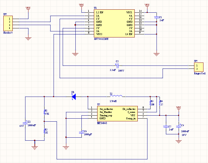
Plan is to build it up on a breadboard to get it running - the bell ringer I have looks slightly different from the one on the above link.
Ah but I hear you ask, where are you getting your power from for the beadboard, well I had this great idea (I actually stole it from http://www.wd5gnr.com/power.htm) and here it is:
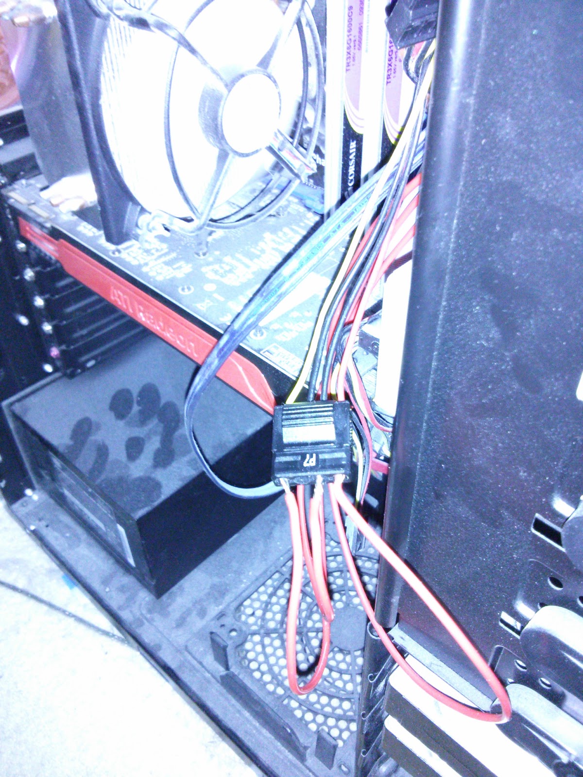
Using a spare power connector from inside my PC and some screw-down posts from an old breadboard I now have this. To connect the wires to the connector I just put a blob of solder on each wire and, using carefully calculated parameters, stuffed them in hard enough so they didn't fall out.

The 10V is actually 12V, but not to worry, I'll only be using the 5V.
[EDIT: This power supply has turned out to be anything but smooth, it fails to drive the PIC correctly - I have resorted to 3 AA batteries in series giving 4.5 volts.]
The inverting switching regulator
Getting 57V from 5V (or 3.5V)
I built this bit first (M34063A) to make sure I could get the required voltage out, the only difference I made was not including the 0.25 Ohm resitor (or 4 x 1 Ohm in parallel). This is replaced by the red wire loop - which I measured at 0.1 Ohm - near enough for me.
When I'd got the required voltage out - 57V - (NOTE: I also got 57V with an input of 3.5V from 2 AA cells) I connected it up to the H-bridge:

I then connected it up to the phone ringer solonoids to see if it would move.
I got one 'ding'!
At this point, and after re-reading the instructions on http://www.sparkfun.com/tutorials/50 I realised I needed an oscillator input signal into the H-Bridge - obvious really :)
I assume this will be representative of the output from the GSM unit (or the Nokia)
On the above website they mention using the PIC to create a 22Hz Oscillator, but as I hadn't got round to figuring out this bit yet, I scratched my head, and in the absence of a frequency generator I decided to use a 555 timer.


To get the required 22Hz I used the following ( from http://totusterra.com/555timercalc.html )
| C1 | R1 | R2 | Period | Frequency | Duty Cycle |
| 0.1 µF | 1 KΩ | 330 KΩ | 0.0458 sec | 21.8306 Hz | 50.1 % |
I will feed this signal into 1A and/or 2A of the H-bridge.
This is as far as I've got, I haven't tested the full ringer yet
More tomorrow...
Retro Mobile Phone
Went to a car boot sale a few weekends ago and bought 2 1970's/80's rotary dial telephones for £10. My intention was to polish them up and sell them on e-bay, but they only make about £10 each and whilst 100% profit may sound good, after the 2 nights of cleaning and polishing I grew quite fond of them!
|
I had a quick look on the net to find out how to make them work with a modern telephone system - like what Sky provide me. I then thought that it would be really cool to have one of these phones as my mobile phone :) I then came accross this site:
http://www.sparkfun.com/tutorials/51
Awsome instructions on how to do it!!
Upon first reading this project sounded fairly straight forward - they certainly made it seem so on the web site...
My plan was to loosly follow their instructions, mainly because I didn't have a C compiler for MPLAB - more on this later.
Plan
Subscribe to:
Posts (Atom)