Sunday 19 October 2014

New dialler code

This is the schematic for the dialler to GMS module.

Below is a representation of a dialled number:

---------------_-_-_-_------------_-_-_-_-_-_----------

would be "35". The long pulse as the rotary is rotated anti-clockwise then the pulses for the number as the rotary returns. So when a long pulse is received, the previous set of pulses has finished and the count of these pulses is saved as the number.

The code is much simpler: (Note to self: this is in a file called push_button.c for some strange reason!)

void getNumber() {
   int16 x = 0;  // number lemgth
   int16 count = 0; // button press count
   int16 pulseCount = 0; // counts the pulses from the rotary
   int32 timer; // This is the timer
   BYTE status; // This if for detecting button state
   char phoneNum[15] = ""; // A character array for the phone number
   char num[4] = "ATD"; // start of the dial string
   strcat(phoneNum,num); // cp the start of the dial string to the phone num AT command


    // do this while the phone is still off the hook
    while (!input(PIN_A1)) {

      if (input (PIN_A0)) // dialer input high
      {
         delay_ms(10); // debounce
         pulseCount++; // This counts the number of clock cycles
         status=0;
         timer=0;
      }

      if (!input (PIN_A0) && status == 0 ) // dialer input low
      {
         delay_ms(10); // debounce switch
         if(pulseCount > 20 && count>0) { // add the count to the AT string
            count--; // decrement as the number is always one more
            if(count > 9)
               count=0;
            sprintf(num,"%ld",count); // makes int count into a string
            strcat(phoneNum,num); // adds num to the phoneNumber
            count=0; // reset the number count
            x++;
         } else {
            count++; // increment the number count
            status=1;
         }
         pulseCount=0;
      }


      // long delay before writing the AT command to GSM
      if( timer > 150000 && x > 0 ) {
         // add the final number
         count--;
         if(count > 9) // if the pulse count is 10 then this is actually a zero
            count=0;
         sprintf(num,"%ld",count); // makes int count into a string
         strcat(phoneNum,num); // adds num to the phoneNumber
         timer=0;
         x=0;     // reset number count
         count=0; // reset pulse count
         printf("%s;\r",phoneNum); // This is the AT command sent to the phone
         while(!input(PIN_A1)); // wait for on hook.
         return;

      }
      timer++;
   }

Saturday 18 October 2014

Phone call placed with PIC!

I have done the first end-to-end demonstration of dialling a number with the rotary dialler and placing a call using the Seimens T30 phone module via a MAX232.

The only problem I had was that I'd bought a passthrough RS232 cable instead of a cross over (aka "null modem cable". This basically makes the output of the RS232 the input to the phone by crossing over the Rx & Tx.

I achieved this by stuffing some wires in until I get my new X-over cable.


Next step is to improve the dialling detection. Currently I am waiting about 1 second after the last received pulse to determine the end of the dial to add the number to the AT string. At the beginning of the dial there is a long pulse as you rotate the rotary anti-clockwise, I will try and use this to indicate the the previous number has been dialled.

Sunday 12 October 2014

Dialler working...


The dialler now works, I have hooked up the rotary dial unit from the GPO phone to the circuit and all numbers are decoded correctly (most of the time) and sent to the RS232 port.


I am waiting for a RS232 - RS232 cable to send the AT command straight to the GSM module.

I had problems with switch bounce from the rotary, but this is almost eliminated with the introduction of 10ms delays after the port on the PIC is read.


The code so far:

#include "C:\Users\Daddy\Documents\CCS\push_button.h"
#include <stdio.h>
#use delay(clock=8000000) // 8MHz
#use rs232(baud=9600, xmit=PIN_B7, rcv=PIN_B5,bits=8)


void getNumber();
void checkOnHook(void);

void main(void)
{
   printf("::main()\n\r");

   // set stuff up
   setup_adc_ports (NO_ANALOGS|VSS_VDD);
   setup_adc (ADC_OFF);
   setup_spi (FALSE);
   setup_oscillator(OSC_8MHz);

   // This is the main loop
   while(true) {
      checkOnHook(); // this will wait for an incomming call
      getNumber(); // gets number from rotary and sends AT command
   }
}

// Checks if the phone is on the hook via A1
void checkOnHook(void) {
   BYTE flag=0;
   printf("::checkOnHook()\n\r");
   // RA1 the ON/OFF Hook detection
   while(input(PIN_A1)){
   // waiting for an incoming call
      if(flag==0) {
         printf("waiting for an incomming call!\n\r");
         flag=1;
      }
   }
   return;
}

// This function returns a char array that is the AT command
void getNumber() {
   int16 x = 0;
   int16 count = 0; // button press count
   int32 timer; // This is the timer
   BYTE status; // This if for detecting button state
   char phoneNum[15] = ""; // A character array for the phone number
   char num[3] = "AT"; // start of the dial string
   strcat(phoneNum,num); // cp the start of the dial string to the phone num AT command
   printf("::getNumber\n\r");

   // do this while the phone is still off the hook
   while (!input(PIN_A1)) {

      if (!input (PIN_A0) && status == 0) //input button
      {
         status = 1;
         delay_ms (10);
         output_low(PIN_C3);
         count++;      }

      if (input (PIN_A0))
      {
         delay_ms(10); // debounce?
         output_high(PIN_C3);
         status = 0;
         timer = 0; //reset timer after a pulse has been received
       }
      // short delay for individual numbers
      if (timer > 40000 && count > 0)
      {

         x++; // increment the index by one
         count--;
         if(count > 9)
            count=0;
         sprintf(num,"%ld",count); // makes count into a string
         printf("count = %ld, %s\n\r",count,num);
         strcat(phoneNum,num); // adds num to the phoneNumber
         printf(">%s\n\r",phoneNum);
         timer = 0;
         count = 0; // reset the counter
      }
      // long delay before returning the AT command
      if( timer > 100000 && x > 0 ) {
         timer=0;
         x=0;
         count=0;
         printf("%s;\n\r",phoneNum);
         while(!input(PIN_A1)); // wait for on hook.
         return;

      }
      timer++;
   }

}

Saturday 11 October 2014

Starting again....

From now on all posts are for the new and improved version of the retro-mobile.

The software will be on a PIC microcontroller - they are obviously much smaller than a Raspberry Pi and use a lot less power! I am using the PIC16F690 coz this is the one on the "low pin count" demo board that comes with the PICkit2 programmer. The plan is to use the PIC16F913 as this has LCD driver capabilities.

The basic functionality will be the same:

  • Receive call from GSM module
  • Decode and dial number from rotary dial
  • Place call with AT command on GSM module.

I have made a start by buying a new GPO phone:


...and a GSM module...

This will be incorporated with the new ringer module - yet to be built. The original mic/speaker will be replaced with some more modern 8ohm ones - should give a clear sound.

I've also completed the C code to decode the dialling and produce the AT command. I've been testing this with an RS232 to USB cable into my Win7 laptop using RealTerm. The AT command is just the unaltered output from the PIC16F690's UART TX PIN. When I was researching this I was under the impression that I needed a MAX232 to produce a text string that could be read by RS232.

I haven't tried to simulate any RS232 input to the PIC yet - this may require a MAX232 - one on order just in case!

C code to follow - it's not as nice as Python (or Java!)


Wednesday 16 April 2014

Latest Version update...the ringer

The ringer circuit is complicated, quite large and subject to blowing up PICs and H-bridges.

Ringer circuit fitted in a phone

This ringer circuit produces a 50V square wave and pulses the existing solenoids which activate the hammer on the two bell. I have decided that it is too big for the phone so another solution is needed so that I can still use the bells in the GPO phone.

Whilst retaining the bells, I have got rid of the 2 solenoids altogether as they are also quite big. So in order to ring the two bells in the phone I have decided that I need a bicycle bell. Well sort of, the mechanism an old fashioned cycle bell uses to spin round and hit the internal sides of the bell itself. This will be replicated using an electric motor, which will spin the 'dingers' against the sides of the 2 bells.

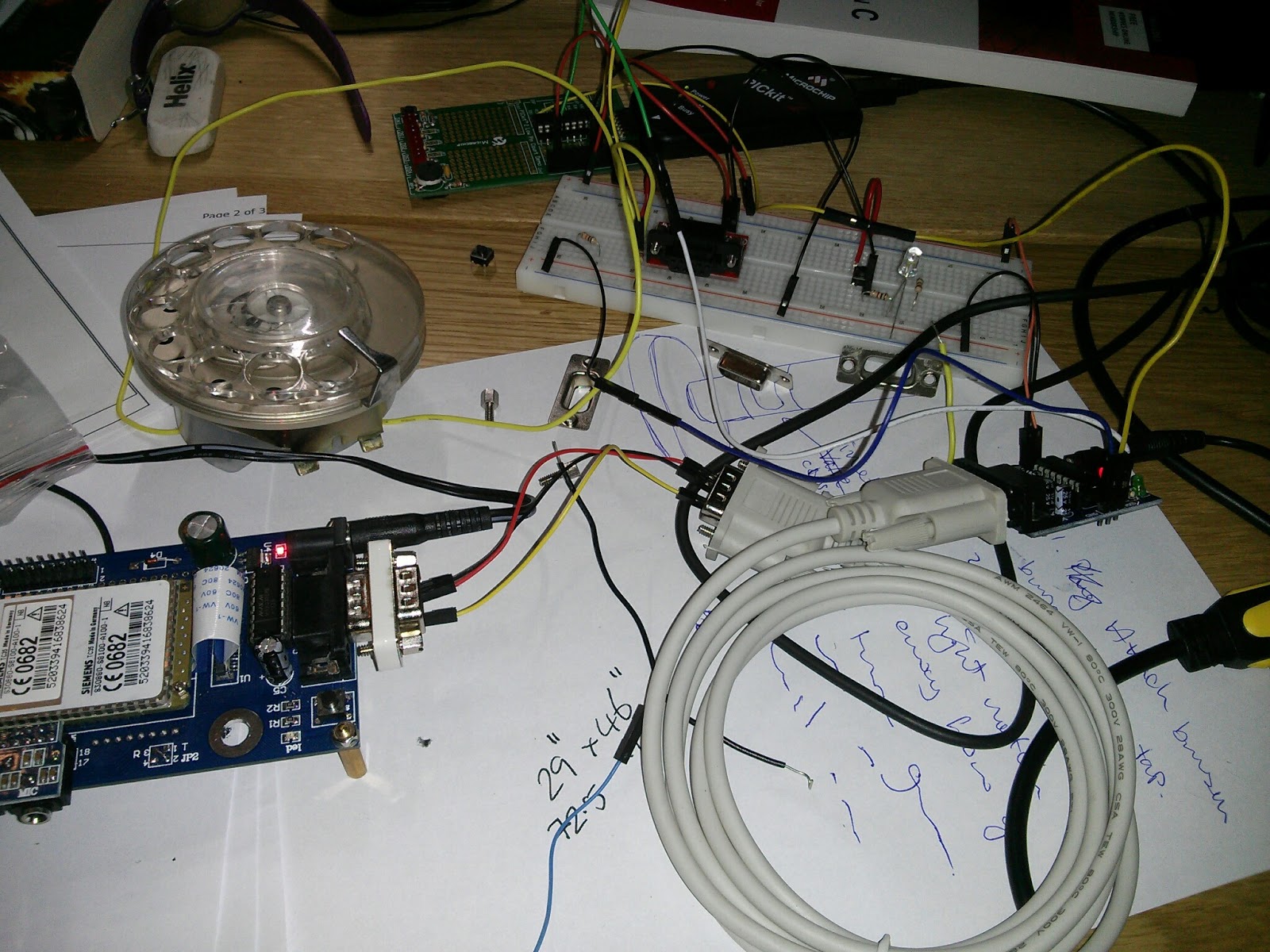
For this purpose I bought a stepper motor as this can be controlled easily with the outputs from a PIC micro controller, which I will  be using anyway to decode the dialled number from the rotary.

I built a circuit using the PICKit2 demo board - which has a 16f690 installed in it - to send the required pulses to the stepper motor controller.


Once I'd found the PIC16F690 datasheet I decided to program the very simple logic using the native assembly language, this initially proved to be quite tricky. (I spent a few years writing assembly for flight control software as a job, but this was nearly 20 years ago!). After searching for tutorials and rereading the datasheet, I had a "light bulb" moment and it all became fairly straight forward.

Using MPLAB 8, I wrote a simple program that sends a pulse-train to the 4 inputs of the stepper motor, the speed of the pulses and hence the stepper is controlled by the POT on the demo board.

Basically the program does the following:

;  Wire 1 2 3 4 5 6 7 8 Port
;  ORG  x x           x C0
;  YEL    x x x         C1
;  PIK        x x x     C2
;  BLU            x x x C3


This is the pulses that have to be sent to the stepper, so orange, then orange + yellow, then yellow etc. this is the half drive for the stepper.

The ports are the ports on the PIC used for output of the pulse.

Here's the source:

;
#include <p16F690.inc>

    __config (_INTRC_OSC_NOCLKOUT & _WDT_OFF & _PWRTE_ON & _MCLRE_OFF & _CP_OFF & _BOD_OFF & _IESO_OFF & _FCMEN_OFF)


; Registers for use with the variable delay loop.
    UDATA
dc1 res 1   ; Reserve 1 byte of data memory and call it dc1
dc2 res 1   ; Reserve 1 byte of data memory and call it dc2
dc3 res 1   ; Reserve 1 byte of data memory and call it dc3


    org 0   ; start vector

Start
    BSF        STATUS,RP0  ; set bit at RP0 in register STATUS to select bank 1
    movlw    0h            ; 00000000 - makes ports C0 & C1 as outputs
    movwf    TRISC         ; moves the 00000000 to TRISC
    BCF        STATUS,RP0  ; clear bit at RP0 in register STATUS to reselect bank 0
    ; Setup the ADC
    ; NOTE: you can set these bits individually using "bsf register,bit"
    movlw    b'001'        ; set the sample rate to /8
    movwf     ADCON1       ; move to ADCON1
    ; The below 2 statements are the same as the 3rd
;    movlw    b'00000001'  ; switch A2D on
;    movwf    ADCON0
    bsf        ADCON0,ADON  ; Sets the ADON bit in ADCON0
Loop
    call A2D
    bsf        PORTC,RC0    ; C0 - using bsf does not alter content of w so means the A2D is detected
    call A2D
;    bsf        PORTC,RC0
;    bsf        PORTC,RC1
    movlw     b'00000011'   ; C0 & C1 - could set ports like this, but done for the above reason.
    movwf    PORTC
    call A2D
    bsf        PORTC,RC1    ; C2
    call A2D
    movlw     b'00000110'   ; C0 & C1 - could set ports like this, but done for the above reason.
    movwf    PORTC
    call A2D
    bsf        PORTC,RC2    ; C3
    call A2D
    movlw     b'00001100'   ; C0 & C1 - could set ports like this, but done for the above reason.
    movwf    PORTC
    call A2D
    bsf        PORTC,RC3    ; C3
    call A2D
    movlw     b'00001001'   ; C0 & C1 - could set ports like this, but done for the above reason.
    movwf    PORTC
    GOTO Loop               ; go to Loop label
   

; 10 millisecond delay loop - altered to speed it up
; setting W to 1 will be a
delay10   
    movwf    dc3       ; move value in w to memory location dc3
dly2
    movlw     .1       ; Repeat inner loop 1 times (was 13) - this speeds it up for stepper motor
    movwf    dc2       ; move .13 to memory location dc2
    clrf     dc1       ; clear dc1
dly1   
    decfsz  dc1,f      ; decrement value at dc1 to 0 then jump
    goto    dly1   
    decfsz  dc2,f      ; decrement value at dc2 to 0 then jump
    goto    dly1
    decfsz  dc3,f      ; decrement value at dc3 to 0 then jump
    goto    dly2
    return


A2D:
    bsf ADCON0,GO     ; start conversion
    btfss ADCON0,GO   

    ; if ADCON0 == 0 then jump (this bit will change to zero when the conversion is complete)
    goto $-1          ; goto previous line
    movf ADRESH,w     ; Copy the value to the w register
    ADDLW     1       ; Add 1 so that the minimum value is always > 1
    call delay10      ; calls the delay script once the value has been read from the POT
    return   


Wednesday 26 March 2014

All Finished...

Not being able to charge the Nokia without dismantling the GPO phone to get to the back of it was a bit of a problem. I thought that perhaps I could put a USB on the back of the phone and somehow plug this into the back of the Nokia.

I ordered a USB to Nokia charger lead but it didn't work :(

Whilst I was trying this an obvious thing struck me - why not just chop the original Nokia charger cable in half, put the 2mm charger in the Nokia, have a socket in the back of the phone and put a 'plug' on the charger cable.


Anyway this all works and the project is complete!

Next version on its way.....


EDIT: I'm not happy with the monstrous battery underneath the phone, and I have found that when I use it I tend to turn it on, show people what it is capable of, they then lose interest as they're not geeky enough, I then turn the phone off. The longest I've had it powered on is about 1 hour. This is easily achievable with the 6AA batteries + voltage regulator which fit inside the GPO phone casing.

Tuesday 25 March 2014

Phone functionality

From the rotary dial you can do the following:

[1] Look at phone book entries
[2] See Nokia battery remaining
[3] Check 'timeup' of the RPi
[4] Program the phone book

All of this is done on the Raspberry Pi, the only thing the phone is used for is sending AT commands to to make calls, answer calls, end calls or check battery.

The phone book is stored in a properties file that is accessed from the main phone Python script.
To program it dial 4 to put it in program mode then enter the phone number to store, prefixed with the position you'd like it stored at.

e.g. 4123 will add the number 123 at position 4 in the phone book.

Dial 4
...enter index then number

Dial 1 to look at the phone book entries...

 To dial a phone book entry it's 1x, where x is the entry position of the number..